Spacebridge HAB PCB Development
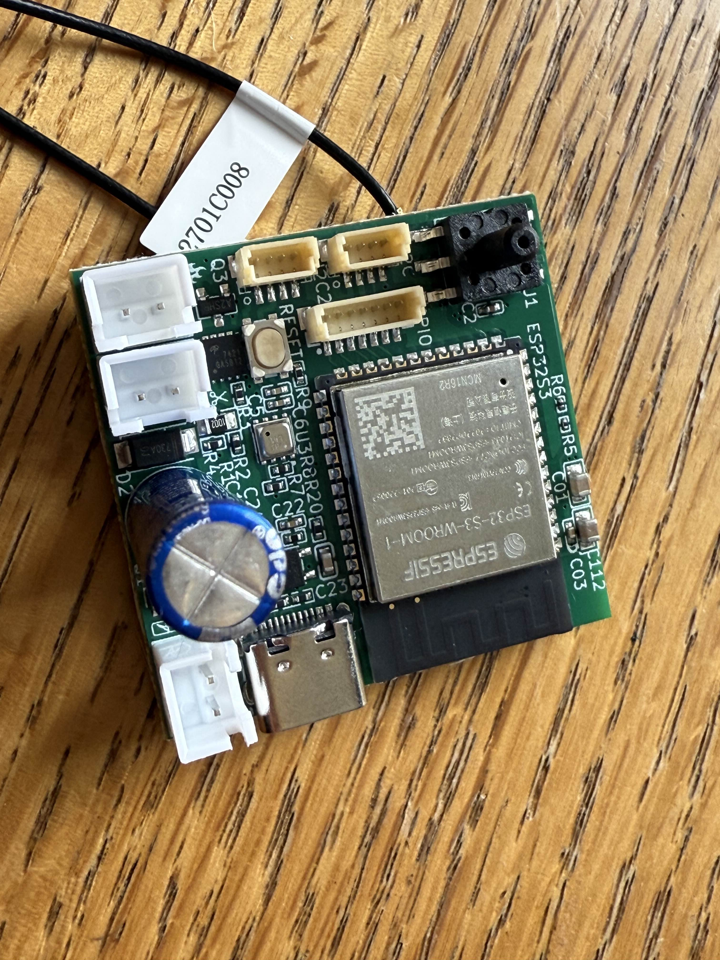
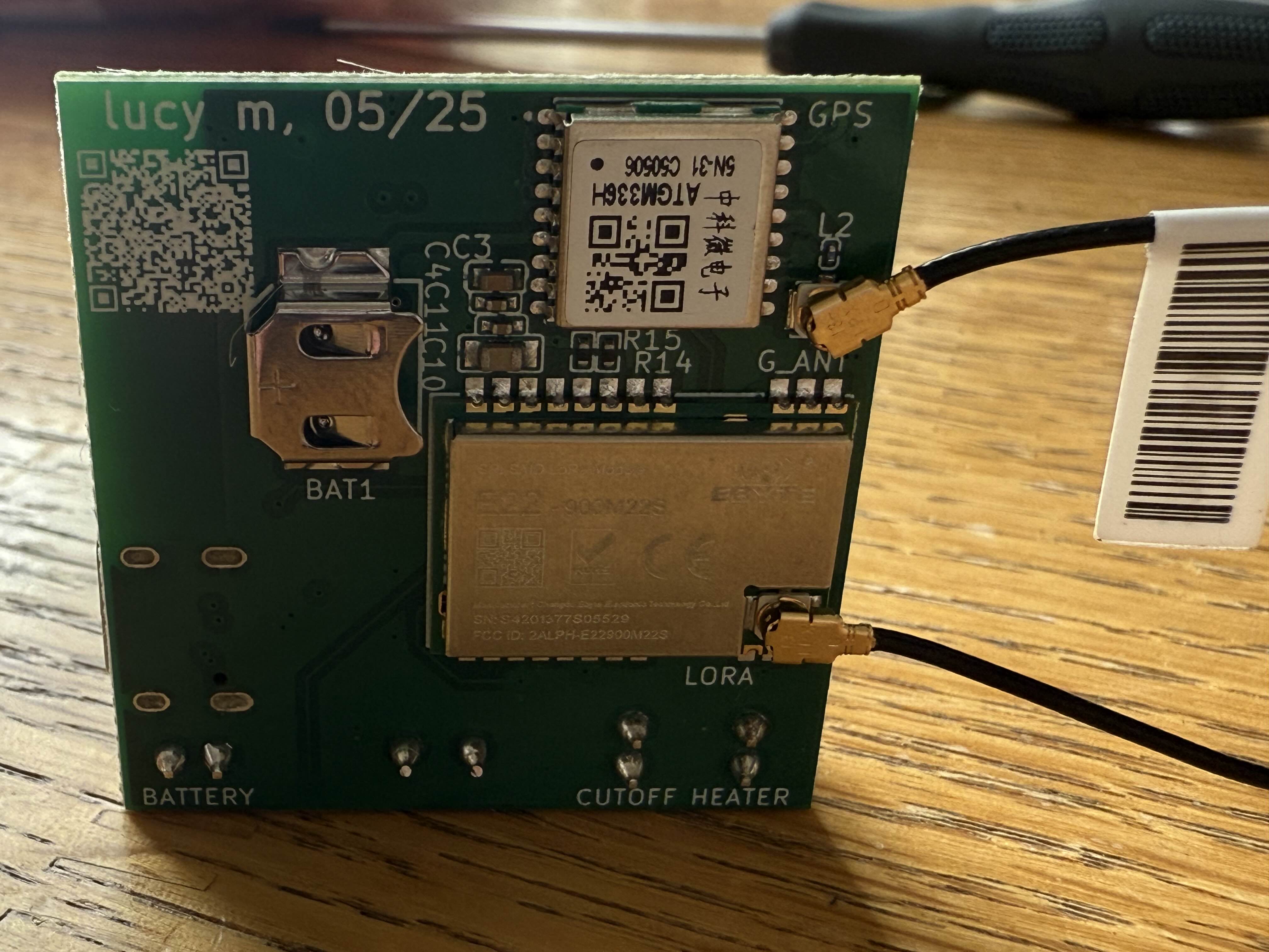
I have been spending a lot of time at Noisebridge. One of their many cool ongoing projects is Spacebridge, a DIY high altitude balloon group. We are using low cost LoRa/meshtastic hardware to send up, track, and recover our own weather balloons! I’ve gotten lot’s of help from some of the folks over at SF HAB, including some folks that put together the amazing Pico Balloon Project. I have a PCB in my hand now, which I’ll be testing in the upcoming weeks. You can follow my GitHub repo.
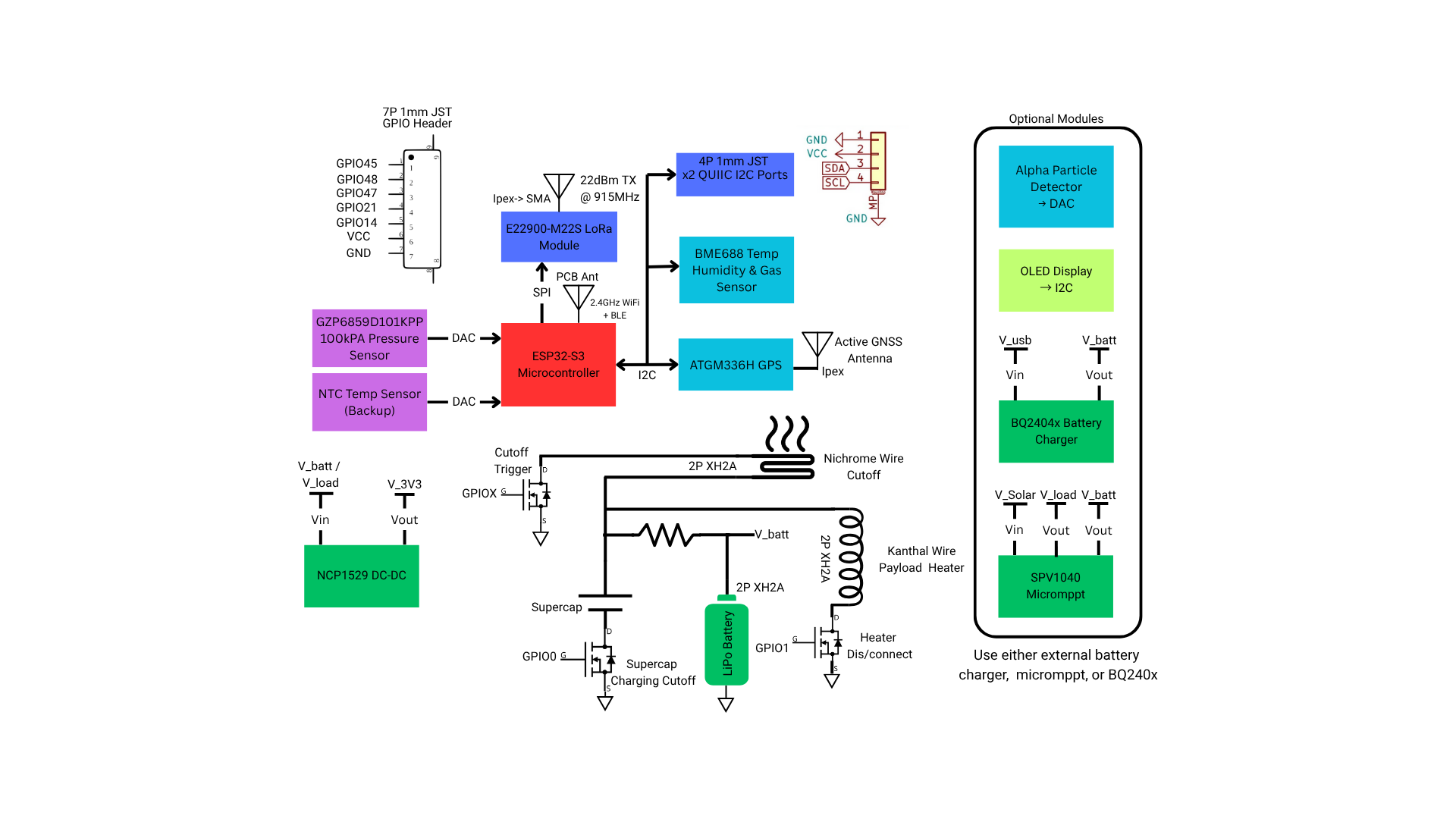
In this post I would just like to give and overview of the hardware and explain some of my design choices.
Here is the mainboard.ato file for reference:
module Mainboard:
    power = new ElectricPower
    power_5V = new ElectricPower; power_5V.gnd ~ power.gnd
    power_3V3 = new ElectricPower; power_3V3.gnd ~ power.gnd
    power_vbat = new ElectricPower; power_vbat.gnd ~ power.gnd
    battery_conn = new XH2A
    battery_conn.p1 ~ power_vbat.vcc; battery_conn.p2 ~ power_vbat.gnd
    C_batconn = new Capacitor; C_batconn.value = 10uF +/- 20%; C_batconn.package = "C0805"
    C_batconn.power ~ power_vbat

    usbc = new USBCConn
    power_usb = new ElectricPower
    power_usb.vcc ~ usbc.usb2.buspower.hv; power_usb.gnd ~ usbc.usb2.buspower.gnd
    power_5V ~ power_usb

    i2c_conn = new _4P1MMJST
    i2c_conn.power ~ power_3V3
    i2c_conn2 = new _4P1MMJST
    i2c_conn2.power ~ power_3V3

    uc = new ESP32S3
    uc.power ~ power_3V3
    uc.i2c ~ i2c_conn.i2c
    uc.i2c ~ i2c_conn2.i2c
    uc.usb2 ~ usbc.usb2

    gpio_conn = new _7P1MMJST
    gpio_conn.p1 ~ uc.io45
    gpio_conn.p2 ~ uc.io48
    gpio_conn.p3 ~ uc.io47
    gpio_conn.p4 ~ uc.io21
    gpio_conn.p5 ~ uc.io14
    gpio_conn.p6 ~ power_3V3.vcc
    gpio_conn.p7 ~ power_3V3.gnd

    pressure_sensor =  new GZP6859D101KPP
    pressure_sensor.i2c ~ uc.i2c
    pressure_sensor.power ~ power_3V3
    C_pres = new Capacitor; C_pres.value = 100nF +/- 20%; C_pres.package = "C0402"
    C_pres.power ~ pressure_sensor.power

    ldo = new Regulator
    ldo.ic.EN ~ ldo.Vin.vcc
    ldo.Vin ~ power_vbat
    ldo.Vin ~ power_usb
    # DO NOT PLUG IN USB-C AND BATTERY AT THE SAME TIME
    ldo.Vout ~ power_3V3
    assert ldo.OUTPUT_VOLTAGE is 3.3V +/- 5%

    lora = new Lora
    lora.power ~ power_3V3
    lora.spi ~ uc.spi2
    lora.lora.spi_cs.line ~ uc.spi2_cs.line

    bme688 = new Nose
    bme688.power ~ power_3V3
    bme688.i2c ~ uc.i2c

    gps = new ATGM336H
    gps.power ~ power_3V3
    gps.i2c ~ uc.i2c
    C_gps1 = new Capacitor; C_gps1.value = 2.2uF +/- 20%; C_gps1.package = "C0603"
    C_gps1.power ~ gps.power
    C_gps2 = new Capacitor; C_gps2.value = 100nF +/- 20%; C_gps2.package = "C0402"
    C_gps2.power ~ gps.power
    gps_bat = new Keystone_2998; gps_bat.power.vcc ~ gps.VBAT; gps_bat.power.gnd ~ power.gnd
    RF_conn = new IPEX
    RF_conn.RF_IN ~ gps.RF_IN
    RF_conn.GND ~ gps.GND
    rf_L = new Murata_Electronics_LQP03TG47NJ02D
    gps.VCC_RF ~ rf_L.p1; rf_L.p2 ~ RF_conn.RF_IN

    cutoff = new Cutoff
    cutoff.power ~ power_vbat # cutoff.power--/\1kohm/\-->|supercap|
    # IO can be remapped as needed for layout, check esp32s3.ato
    cutoff.SC_GATE ~ uc.io0 # Dis/connect supercapacitor
    cutoff.CUTOFF_GATE ~ uc.io1 # Fire cutoff, active high
    cutoff.SC_Sense ~ uc.io37

    ntc = new NCP03WF104F05RL
    R_div = new Resistor; R_div.value = 10kohm +/- 5%; R_div.package = "R0201"
    R_div.p1 ~ uc.power.vcc; R_div.p2 ~ ntc.p1; ntc.p2 ~ uc.power.gnd
    signal TEMP; TEMP ~ ntc.p1
    uc.io16 ~ TEMP